1 Scope
This international standard specifies the essential dimensions of physical characteristics for metallic pipes, pipes with single flares, tapped holes, male fittings and hose end fittings used in hydraulic braking systems for road vehicles.
2 Normative reference
The following standard contains provisions which, through reference in this text, constitute provisions of this International Standard. At the time of publication, the edition indicated was valid. All standards are subject to re-vision, and parties to agreements based on this International Standard are encouraged to investigate the possibility of applying the most recent edition of the standard indicated below. Members of IEC and ISO maintain registers of currently valid International Standards.
ISO 9227:1990, Corrosion tests in artificial atmospheres-Salt spray tests.
3 Pipes
Pipes shall be made from double-walled rolled pipe of dimensions conforming to table 1.
Pipes may be flanged at both ends with male fittings (see figure 1). Flanges shall be as shown in figure 2 and table 2.
Pipes with additional plastic coating may be used; however, these pipes shall be compatible with male fittings, tapped holes, and flares as specified in this International Standard.
Steel tubes shall have the following mechanical characteristics:
tensile strength1): >290 MPa
yield point: >200 MPa
elongation at break1) > 25 %
hardness: <55 HR30T
1) For pipes which are to be bent
The inner and outer surfaces of the tube shall be free from oxidation. The outer surface shall be protected against corrosion and shall withstand the NSS salt spray test in accordance with ISO 9227 for at least 96 h.
Table 1 Dimensions of Pipes
| Outside diameter for bare pipe 1) | D | nom. | 4.75 | 6 | 8 | 10 |
| tol. | ±0.07 | ±0.07 | ±0.07 | ±0.07 | ||
| Wall thickness | e1 | nom. | 0.7 | 0.7 | 0.7 | 0.7 |
| tol. | ±0.07 | ±0.07 | ±0.07 | ±0.07 | ||
| Outside diameter, with surface protection | D1 | max. | 4.97 | 6.22 | 8.22 | 10.22 |
| Minimum burst pressure | MPa2) | 110 | 85 | 67.5 | 55 | |
| Average mass per meter | kg/m | 0.07 | 0.09 | 0.12 | 0.16 |
NOTE – The circumferential tolerance of the pipes shall be contained within the outside diameter tolerance.
1) Bare pipe means a pipe without surface treatment. Pipes which have been manufactured from surface-treated sheet material are considered to be bare pipes.
2) 1 MPa=10 bar
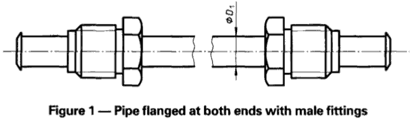
Figure 1 – Pipe flanged at both ends with male fittings
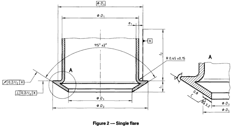
Figure 2 – Single Flared
Table 2 – Dimensions of single flares
Dimensions are in millimeter
| Tube Diameter D nom. | D1 max. | D2 js14 | D3 +0.3 -0.2 | D4 ref. | D5 min. | l1 ±0.3 | l2 min |
| 4.75 | 4.97 | 7.1 | 3.2 | 6 | 5.5 | 2.5 | 17 |
| 6 | 6.22 | 8.4 | 4.5 | 7.3 | 6.8 | 2.5 | 18 |
| 8 | 8.22 | 10.7 | 6.5 | 9.3 | 8.8 | 2.7 | 24 |
| 10 | 10.22 | 12.7 | 8.5 | 11.3 | 10.8 | 3 | 28 |
4 Tapped Holes for Cone Sealing
Dimensions of tapped holes for cone sealing shall be as shown in figure 3 and table 3. At the discretion of the manufacturer, the hole entry may be as shown in figure 4.
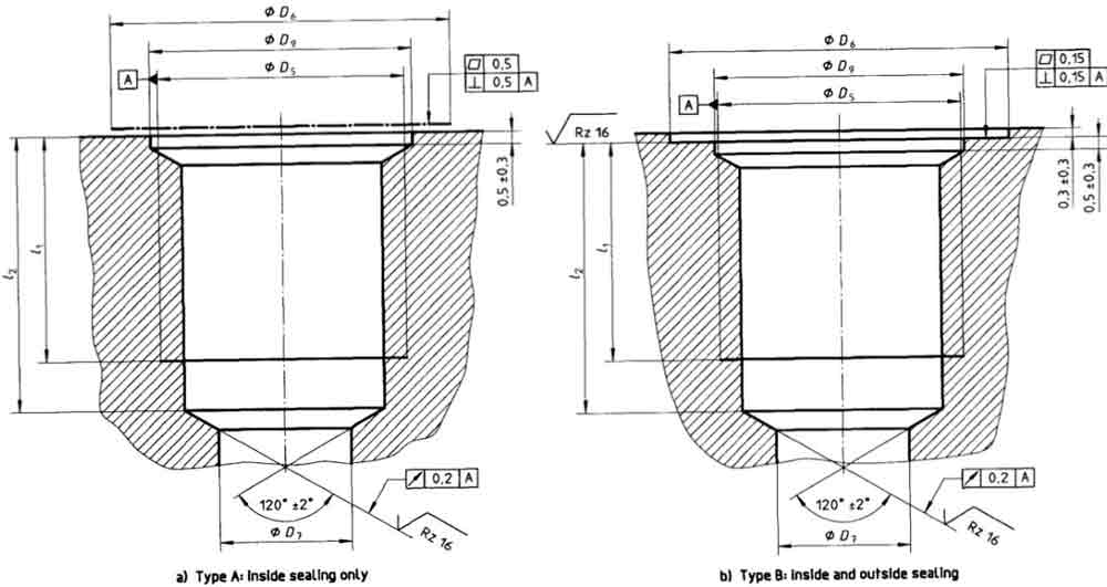
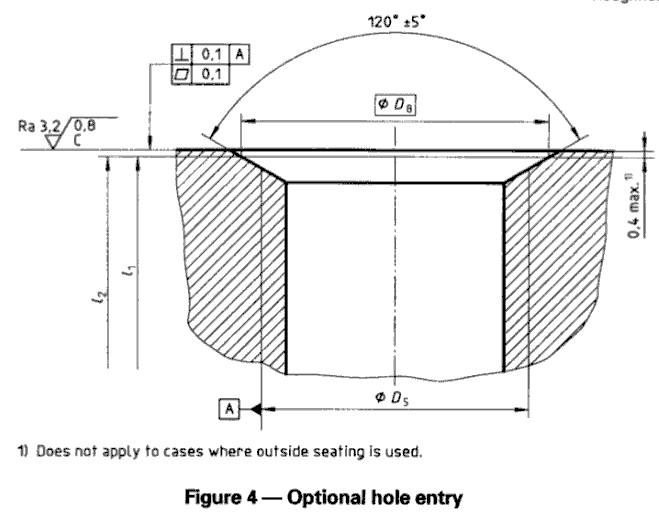
Figure 4 – Optional hole entry
Table 3 – Dimensions of tapped holes for cone sealing
| Tube Diameter D nom. | D5 6H | D6 min | D7 0 -0.4 | D8 ref. | D9 ±0.2 | l1 min. | l2 ±0.25 |
| 4.75 | M10x1 | 16 | 3.3 | 10.5 | 10.2 | 7.5 | 10 |
| 6 | M12x1 | 18 | 4.6 | 12.5 | 12.2 | 9.5 | 12 |
| 8 | M14x1.5 | 20 | 6.6 | 14.5 | 14.2 | 13.25 | 16.5 |
| 10 | M16x1.5 | 22 | 8.6 | 16.5 | 16.2 | 14.25 | 17.5 |
5 Male fittings
Dimensions of male fittings shall be as shown in figure 5 and table 4.
Fittings shall withstand the following minimum torques:
fitting M10 x 1 : 30 N-m;
fitting M12 x 1:30 N-m;
fitting M14 x 1,5: 35 N·m;
fitting M16 x 1,5: 35 N-m.
The inner and outer surfaces of the fitting shall be free from oxidation. The outer surface shall be protected against corrosion and shall withstand the NSS salt spray test in accordance with ISO 9227 for at least 96 h.
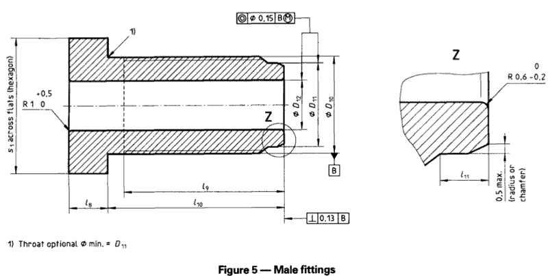
Figure 5 – Male Fittings
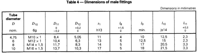
6 Hose end fittings
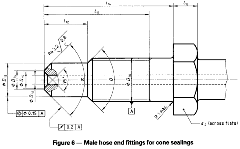
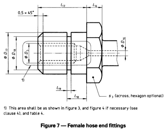
Hose end fittings may be of the male type, conforming to figure 6 and table 5, or of the female type, conforming to
figure 7 and table 6. They shall withstand a minimum torque of 35 N.m.