Click here to learn more about our brake line and related products.
1 Scope
These specifications cover two types of steel tubing suitable for automotive uses. There are requirements for the base metal, the optional coating materials, and the coated tubing. These requirements are applicable to the product coming out of the tube mills and the coating application lines, which are sometimes separate facilities. This tubing is used in the production of customized parts and assemblies. It is recommended that those parts and assemblies be validated for corrosion performance, conductivity and continuity, strength, appearance, and other critical properties unique to the particular application.
1.1 GM123M.
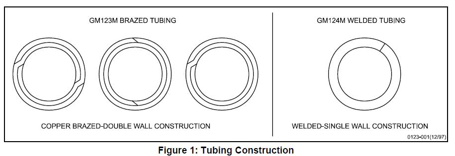
Covers double wall construction tubing wherein the two walls and the joints are copper brazed in a reducing atmosphere to produce tubing satisfactory for hydraulic lines. It should not be used for fuel lines because residual copper can contribute to the formation of sour gas. See Figure 1.
1.2 GM124M.
Covers single wall construction tubing wherein the joint is electric resistance welded. It is recommended for fuel lines, power steering lines, transmission oil cooler lines, lubricating oil lines, vacuum lines, etc. See Figure 1.
1.3 Tubing Designation Code.
It is recommended that the codes in paragraph 3.1 be used on drawings and purchase orders to designate tubing type, outside diameter, wall thickness, manufactured condition finish and the internal diameter (ID) coating.
1.4 Typical Application.
GM123M is typically used for hydraulic brake lines whereas GM124M is typically used for fuel lines, power steering lines, transmission oil cooler lines, lubricating oil lines, vacuum lines, etc.
2 References
Note: Only the latest approved standards are applicable unless otherwise specified.
2.1 External Standards/Specifications.
ASTM A254
SAE J463
ASTM A875
SAE J526
ASTM B117
SAE J527
ASTM B750
SAE J533
ASTM E8
SAE J1290
SAE J403
2.2 GM Standards/Specifications.
9985670
GM9505P
GM4298P
GM9508P
GM4465P
GM9509P
GM4653M
GM9540P
GM6277M
GMW3001
GM9071P
GMW3059
GM9102P
2.3 Additional References.
Information regarding GMPT fuels can be obtained by contacting GM Powertrain Materials Engineering.
• GMPT-6-006 TF2 gasoline
• GMPT-5-005 Bio-Diesel
• GMPT-5-001 #2 Diesel
• GMPT-6-019 Oxidized Gasoline
• GMPT-6-023 E85 Low pHe
3 Requirements
3.1 General Requirements.
Basic tubing material shall be cold rolled 1006, 1008 or 1010 steel per SAE J403. Brazing material should be copper or copper alloy as designated in SAE J463, Copper Alloy UNS C51000.
GM123M (I/II/III/IV/V)
GM124M (I/II/III/IV/V/VI)
‘I’ = First item in parenthesis, a B or a W.
B = Brazed, W = Welded
‘II’ = Outside diameter of as-brazed or as-welded tubing (mm)
‘III’ = Wall thickness (mm)
‘IV’ = Manufacturing Process (*)
‘V’ = Automotive
‘VI’ = Internal Diameter Coating(**)
(*) Process Abbreviations:
A = Annealed
P = Plain
U = Unannealed (as welded)
G = Zinc-aluminum-alloy Metal Coating
F = Copper Fused
E = Extended Corrosion Protection Paint Coating
N = Extruded Nylon 11 or 12
C = Copper Plate – Standard copper plate thickness is 0.009 mm minimum. If other than standard thickness is required, numeral(s) should be used immediately following the letter C, e.g., C13 indicates 0.013 mm minimum.
(**) Internal Diameter Abbreviations
Blank = Plain
P = Plain
Ni = Ni Plating
Example:
GM124M (W/6.00/0.7/AGE/V/Ni) – indicates welded single walled tubing, 6 mm O.D., 0.7 mm wall thickness, annealed tubing, protected from corrosion with a base coating of a zinc-aluminum-alloy metal followed with a topcoat paint layer, approved for automotive application, with a Nickel plated ID.
3.2 Mechanical Properties.
The following requirements shall apply only to the more common types of steel tubing; that is, welded-annealed and brazed-as manufactured. Properties of other classes of tubing, such as welded mechanical tubing or work hardened tubing, shall be as specified through special agreement between supplier and purchaser.
3.2.1 Tensile tests shall be conducted on finished tube in accordance with methods of testing tubes outlined in ASTM E8. Tensile properties shall be per SAE J526 for welded tubing and per SAE J527 for brazed tubing.
3.2.2 Tubing shall be capable of being expanded over a tapered mandrel having a slope of 1 in 10 until the outside diameter at expanded end is increased 20% without cracking or showing flaws (ASTM A254, Paragraph 6.3). Prior to expansion test, tubing shall be cut off square, edge crowned, and deburred. It shall be held firmly and squarely in the die, and punch must be guided on the axis of the tubing.
3.2.3 Unless otherwise specified, tubing shall be capable of withstanding the following internal static hydraulic pressure:
• Through 10.0 mm OD………………..35 MPa
• Over 10.0 through 16.0 mm OD…….15 MPa
Note: Subsequent cold working of the tube (coiling, straightening, bending, drawing, etc.) will increase the strength and hardness of the tube. Considerably higher strength and hardness for specific applications can be obtained by cold working or case hardening of the tube.
3.3 Dimensions.
Tubing shall conform to the dimensions and tolerances listed by the purchaser.
3.3.1 Welded Tubing.
Nominal diameter and wall thickness shall conform to those listed in SAE J526. Maximum OD for the Zinc-aluminum alloy plus Nylon 11 or 12 topcoat, GN, can be found in Table 2.
3.3.1.1 Nickel Coated ID Weld Bead.
In order to ensure good re-flow of the nickel at the weld, it is important that the weld bead have a smooth cross-sectional profile and minimum bead dimensions. Report the bead height dimension (The typical bead height shall be 0.15mm or less. Continue monitoring the bead height until a maximum bead height requirement has been established).
Typical examples of good versus undesirable bead profiles are shown below in Figure 2.
3.3.2 Brazed Tubing.
Nominal diameter and wall thickness shall conform to those listed in SAE J527. Maximum OD for the Zinc-aluminum alloy plus Nylon 11 or 12 topcoat, GN, can be found in Table 2.
3.3.3 Flare Ends.
3.3.3.1 SAE-type flares shall conform to the dimensions and tolerances shown in SAE J533.
3.3.3.2 ISO-type flares shall conform to the dimensions and tolerances shown in SAE J1290.
3.3.3.3 FLARED ENDS. In the case of GM123M (inverted flare), pipe flare ends shall conform to the Supplementary Requirements in ASTM A254 section S1.
3.4 Finishes.
Finish on the inside and outside of the tubes shall conform to the specified finish as shown in Table 1.
Table 1: External Finish Codes and Requirements
| Finish | Finish Code | Description and Material Requirements |
| Plain | P | No coating; base metal only (1006, 1008 or 1010 steel per SAE J403) |
| Zinc-Aluminum Alloy | G | Hot-dip zinc-aluminum alloy coating. Chemical Composition: 5% aluminum-balance zinc alloy per ASTM B750 Coating mass: 50 g/m2 per ASTM A875, Section 8. Thickness shall be three micrometers min anywhere on the tube per Appendix A. |
| Zinc-Aluminum Alloy – Extended Corrosion Protection | GE | Zinc-aluminum alloy as described above, followed by an approved pretreatment process and an approved aluminum-rich epoxy coating. Thickness Measurements: The aluminum-rich epoxy paint of the GE finish shall have a min thickness of three microns anywhere on the tube as measured by the procedures in Appendix A. Actual thickness of the coatings in the GE finish shall be monitored circumferentially and longitudinally for each tube line. A sampling plan shall be referenced in the control plan. |
| Copper Plate | C | Electroplated tubing |
| Zinc-Aluminum Alloy – Extruded Nylon 11 or 12 | GN | Zinc-aluminum alloy as described above, followed by a topcoat of Nylon 11 or 12. Appearance: The topcoat shall be uniform in color and free from discontinuities such as flow lines, pin holes, craters, or abnormal roughness. The topcoat shall be black in color unless otherwise specified on the engineering drawing Film Thickness: The Nylon 11 or 12 topcoat shall have a min thickness of 150 μm when tested by microscopic examination per Appendix A. Max thickness of the coating shall be controlled by the max OD (Table 2). Actual thickness of the coatings in the GN finish shall be monitored circumferentially and longitudinally for each tube line. A sampling plan shall be referenced in the control plan. |
| Nickel Plating | Ni | Inside diameter electroplated nickel coating. Thickness Measurements: The electroplated nickel ID plating thickness of the finished tube shall have a minimum thickness of 3 microns everywhere on the ID of the tube as measured by the procedures in Appendix A. Actual plating thickness of the Ni finish shall be monitored circumferentially and longitudinally for each tube line. A sampling plan shall be referenced in the control plan. |
| Other | Z | TBD |
Note: GN topcoat should not be used on liquid fuel line applications until full material approval is given for liquid fuel line applications.
Table 2: Maximum OD for GN Coating
| Tube Size, Nominal (mm) | Coated Tube OD, Max (mm) |
| 4.76 | 5.28 |
| 6 | 6.65 |
| 6.35 | 6.87 |
| 7.94 | 8.46 |
| 8 | 8.52 |
| 9.53 | 10.05 |
| 10 | 10.52 |
| 11.11 | 11.65 |
| 12.7 | 13.24 |
| 14.29 | 14.83 |
| 15.88 | 16.42 |
3.5 Environmental Resistance (GE, GN and Ni).
3.5.1 Salt Spray Testing (GM4298P).
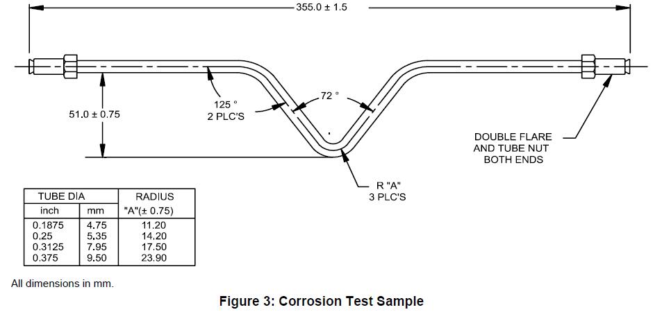
Coated tubing shall be subjected to the following corrosion tests and evaluation methods. All corrosion tests shall be conducted on fabricated parts or on the test sample in Figure 3. Test samples as described in Figure 3 shall be aligned in the test chamber with the formed elbow facing down but not contacting the test fixture, except as noted. Fabricated parts shall be aligned in the test chamber as agreed upon between the testing facility and reviewing authority. The frequency for running all of the corrosion tests shall be documented in the control plan.
Note: Surface contaminants can cause staining in a corrosion test. Stains in the absence of corrosion should not be recorded as a corrosion failure.
3.5.1.1 Zinc-Aluminum Alloy – Extended Corrosion Protection (GE).
The GE extended corrosion protection tubing must withstand 1000 h of salt spray exposure per GM4298P with no more than 1.5 mm of creepback (See GM9102P) from longitudinally placed scribes and no other loss of adhesion after GM4298P exposure and air blow-off.
3.5.1.2 Zinc-Aluminum Alloy – Extruded Nylon 11 or 12 (GN) Low Temperature Chip Resistance plus Salt Spray (GM9508P, GM4298P).
Subject formed tubing samples (see Figure 3) to the chip resistance test, GM9508P, Method B, five times each. The tubing shall be placed in the gravelometer such that the plane created by the bend is parallel to the panel. Within 24 h of gravelometer exposure, place the specimens into salt spray per ASTM B117 or GM4298P.
The tubing shall show no base metal corrosion extending more than 1 mm from gravel impacted area after 2000 h. Non gravel impacted areas shall be free from rust after 2000 h.
3.5.2 Humidity Testing (GM4465P, GM9071P).
Extended corrosion protected tubing (GE) shall be subjected to 96 h of humidity testing per GM4465P. Immediately after the humidity test, the tubing shall be wiped dry and tape adhesion tested per GM9071P, except a linear scribe should be made longitudinally on the tube. There shall be at least 99% adhesion.
3.5.3 Nickel Plated (Ni) Humidity Testing (GM4465P, GM9071P).
The nickel plated ID coating shall be exposed to the following humidity test using 100 mm straight samples and on test samples as shown in Figure 4. Three test samples of each configuration shall be sectioned longitudinally, exposing the inside surfaces of the tube. The cut edges of the test samples shall be sufficiently protected to prevent rust bleed out. The samples shall be placed in the test chamber with the inside surfaces facing upward. The straight samples shall be placed approximately at a 30° angle from the verticle in order to allow for moisture run off. The nickel coating must withstand 168 h of humidity exposure per GM4465P with no red rust outside the weld (heat affected) zone. Any corrosion
within the weld (heat affected) zone will require GM Materials Engineering approval.
3.5.4 Solvent Rub Test (GM9509P).
Extended corrosion protected tubing, (GE), when MEK solvent rub tested per GM9509P, shall exhibit a rating of one or better after testing to 50 double rubs. This test shall be run on each production batch of tubing and shall be documented in the control plan. A production batch shall be defined in the quality system documents.
3.5.5 Fluid Resistance.
3.5.5.1 Extended corrosion protected tubing (GE) shall show no softening or film defects when immersed for 24 h in brake fluid (GM4653M), TF2 gasoline (GMPT-6-006), Bio-Diesel (GMPT-5-005), #2 Diesel (GMPT-5-001), Oxidized Gasoline (GMPT-6-019) and E85 Low pHe (GMPT-6-023). This test shall be run with brake fluid at least once a week on production parts or samples per Figure 3 and shall be documented in the control plan.
Note: Information regarding GMPT fuels can be obtained by contacting GM Powertrain Materials Engineering. Fuels must be purchased from GM approved suppliers. Use the most up-to-date suffix level for each fuel, per the GM Powertrain engineer.
3.5.5.2 Zinc-Aluminum Alloy – Extruded Nylon 11 or 12 (GN).
3.5.5.2.1 Sample Preparation.
Samples shall be a minimum 80 mm long. Make two parallel cuts 2.4 ± 0.1 mm apart longitudinal to the tube using a Stanley utility knife with a #99E blade or equivalent. The cuts must be through the nylon layer and primer down to the substrate along the entire length of the tube. Place six samples per fluid in a sealable container. Fill the jar with a required fluid from Table 3 such that approximately half of each sample is submerged. Seal the container. Soak the samples for the appropriate time and temperature as required in Table 3. After the required soak time remove the samples from the fluid and dry them with a paper towel.
Table 3: Fluid Resistance
| Fluid | Time (h) | Temp (°C) |
| Distilled Water | 504 | 23 ± 2 |
| Brake Fluid (GM4653M) | 504 | 60 ± 2 |
| Oxidized Gasoline (GMPT-6-019) | 504 | 23 ± 2 |
| TF2 (GMPT-6-006) | 504 | 23 ± 2 |
| Bio-Diesel (GMPT-5-005) | 504 | 23 ± 2 |
| #2 Diesel (GMPT-5-001) | 504 | 23 ± 2 |
| E85 Low pHe (GMPT-6-023) | 504 | 23 ± 2 |
| Engine Coolant (GM6277M) | 504 | 23 ± 2 |
| Windshield Washer Solvent (9985670) | 504 | 23 ± 2 |
3.5.5.2.2 Coating Separation Procedure.
Using the utility knife, make a perpendicular cut between the two parallel cuts near the end of the sample which was submerged in fluid. With the edge of the blade in the perpendicular cut, try and lift up or peel back the strip of nylon until the section can be grabbed with a pair of pliers or equivalent. Peel until either the section breaks or the section is removed from the entire length of the tube. If the strip was not completely removed, repeat the procedure from the vapor end of the sample.
3.5.5.2.3 Acceptance Criteria.
There shall be no evidence of any blistering or delamination of the nylon prior to the coating separation procedure. After the coating separation procedure, the sample is considered acceptable if the nylon strip breaks. If it does not break, the strip must show cohesive failure of the primer. Cohesive failure is defined as visible evidence that primer remains on the nylon strip and tube substrate.
3.5.5.3 Electroplated Nickel ID Coating.
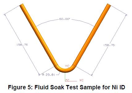
The nickel plated ID tubing shall be exposed to the fluids listed below using 100 mm straight samples and on test samples as shown in Figure 5. Three test samples of each configuration shall be exposed for 504 h at 60°C (90°C for Bio-Diesel and #2 Diesel) when filled ½ way with the following fluids: Bio-Diesel (GMPT-5-005), #2 Diesel (GMPT-5-001), Oxidized Gasoline (GMPT-6-019), Corrosive 2-Phase Gasoline (GMPT-6-020*) and E85 Low pHe (GMPT-6-023). After 504 h of immersion, the samples shall be sectioned longitudinally and inspected – no corrosion or pitting are allowed outside the weld (heat affected) zone. Any corrosion within the weld (heat affected) zone will require GM Materials Engineering approval.
Note: Information regarding GMPT fuels can be obtained by contacting GM Powertrain Materials Engineering. Fuels must be purchased from GM approved suppliers. Use the most up-to-date suffix level for each fuel, per the GM Powertrain engineer.
3.5.6 Cyclical Corrosion Testing (GM9505P, Cycle J or GM9540P).
3.5.6.1 Extended corrosion protected tubing (GE) shall be subjected to a performance test consisting of properly formed tubing samples (See Figure 3) subjected to 10 cycles (20 weeks) of GM9505P Cycle J or to GM9540P, test duration D. After cycling, the tubing shall exceed a pressure test of 14 MPa for tubing through 10.0 mm OD or 7 MPa for tubing over 10 mm OD. In order for this test to be valid, there cannot be corrosion from inside out that causes a failure in the pressure test. Therefore, it is recommended that the tube fittings be fastened into a solid block of aluminum, to keep the system closed during exposure.
Furthermore, sealing the fittings with a wax is acceptable to keep these parts functional for the pressure test.
The minimum acceptable frequency for running this test shall be agreed upon by the supplier and GM Supplier Contact and shall be documented within the quarterly PPAP submission.

3.5.6.2 Zinc-Aluminum Alloy – Extruded Nylon 11 or 12 (GN).
Knife Cut plus Cyclical Corrosion GM9505P, Cycle J, 10 cycles (20 weeks). Using straight tubing with standard fittings, scribe parallel lines, 4 cm long and 2.4 ± 0.1 mm apart, near the center. Within 24 h of scribing, perform cyclical corrosion per GM9505P, Cycle J, 10 cycles (20 weeks). After cycling, the tubing shall exceed a pressure test of 14 MPa for tubing through 10.0 mm OD or 7 MPa for tubing over 10 mm OD. In order for this test to be valid, there cannot be corrosion from inside out that causes a failure in the pressure test. Therefore, it is recommended that the tube fittings be fastened into a solid block of aluminum, to keep the system closed during exposure.
Furthermore, sealing the fittings with a wax is acceptable to keep these parts functional for the pressure test.
Results shall be reported with the submission for engineering approval.
3.6 Form, Size, and Quality.
Automotive steel tubing shall be commercially round, smooth and free from rust and defects which impair processing or serviceability. Joint bead on outside diameter of tubing may be acceptable by agreement with individual purchasers. However, this shall not exceed outside diameter tolerance and shall not interfere with flare forming operation or with the accomplishment of leak-tight coupling joints. A bead on the inside is permissible but must be held to a minimum of good welding or brazing practice. When specific lengths are specified, they shall be reasonably straight, and ends shall be free from burrs.
3.6.1 Tubing for use as hydraulic brake lines shall have internal cleanliness conforming to a maximum of 0.20 g per square meter of internal surface as determined by ASTM A254, Section 8 Inside Surface Cleanliness.
3.6.2 All coatings shall withstand normal forming, handling and storage conditions encountered by tubing without evidence of chipping, flaking or loss of adhesion to base metal. Longitudinal or peripheral burnishing resulting from processing and handling is acceptable.
3.7 Special Requirements.
Special requirements pertaining to dimensions, finishes, physical properties or applications shall be as agreed upon between supplier and purchaser.
3.8 Packing and Marking.
Material shall be shipped as specified by purchaser. Containers shall be legibly marked with supplier’s name and address, material specification number and name, purchase order number, net weight, and any other information specified by the purchaser.
4 Manufacturing Process
Not applicable.
5 Rules and Regulations
5.1 All materials supplied to this specification must comply with the requirements of GMW3001, Rules and Regulations for Material Specifications.
5.2 All materials supplied to this specification must comply with the requirements of GMW3059, Restricted and Reportable Substances for Parts.
6 Approved Sources
Engineering qualifications of an approved source is required for this specification. Only sources listed in the GM Materials File (i.e., MATSPC) under this specification number have been qualified by engineering as meeting the requirements of this specification.
Appendix A – A Procedure for Measuring Thickness of the Dual Layer Coating on Automotive Steel Tubing
A1 Scope
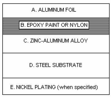
The procedure is used to determine compliance with a specified minimum coating thickness and to set up correlation with equipment used for monitoring coating thickness in production. The coating system is a low carbon steel tube substrate with either a bare or Ni plated ID, and a zinc-aluminum alloy OD followed by an aluminum rich epoxy coating or extruded Nylon 11 or 12 coating. The finishes can be found listed in GM123M/GM124M, under Table 1 designation (GE), (GN) or (Ni). The procedure is used to determine compliance with a specified minimum coating thickness and to set up correlation with equipment used for monitoring coating thickness in production. The coating system is a low carbon steel tube substrate with either a bare or Ni plated ID, and a zinc-aluminum alloy OD followed by an aluminum rich epoxy coating or extruded Nylon 11 or 12 coating. The finishes can be found listed in GM123M/GM124M, under Table 1 designation (GE), (GN) or (Ni).
A2 Referenced Standards
GM123M
GM124M
A3 Equipment Used
A3.1 Metallograph.
A3.2 Metallurgical Polishing Equipment.
A4 Sample Preparation
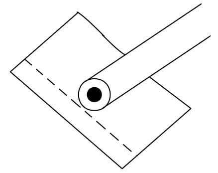
The tubing shall be sectioned at several transverse locations to determine compliance to a minimum thickness of coating. The sections are to be deburred, cleaned and dried. Each section is wrapped separately in aluminum foil, and the foil is then molded to the part with the fingers (See Figure A1) prior to mounting. Only one layer of foil is required, and the tube should be covered in its entirety, being careful not to puncture the foil. The excess folds and overlaps should be above the plane of polish. Exercise care in mounting, being sure each section is perpendicular to the plane of polish. The samples should be compression mounted with a thermosetting powder such as diallylphthalate. Compression molding also serves to mold the foil tight to the contour of the coating, providing excellent edge retention and a well defined interface. The mount(s) should be slowly cooled to ambient temperature to prevent edge separation.
A5 Procedure
A5.1 Metallographic Preparation.
A5.1.1 The mounted section is ground with a series of successively finer grinding papers beginning with 180 grit, then 320, and finally 600 grit, with a good flow of water as a lubricant. All grinding is done with light to moderate pressure to minimize smearing of the coating.
A5.1.2 The mount is washed between each grind operation to remove any of the coarser media from the previous step. It also serves to prevent contamination of subsequent grinding and polishing wheels.
A5.1.3 The specimen should be rotated 90 degrees between each grinding step to minimize pull-out of the softer coatings and prevent smearing of the epoxy paint or nylon to zinc-aluminum coating interface and zinc-aluminum to steel interface.
A5.1.4 After the final grinding operation wash thoroughly, alcohol rinse and dry prior to the final polishing sequence.
A5.1.5 Final polishing is carried out using cloth wheels and diamond polishing compounds. Recommended sequence is a six micron followed by 3, 1 and 0.25 micron. A 0.05 micron alumina suspension can be used as a last step if a scratch free surface is desired. However, the alumina is alkaline and could promote staining of the zinc layer, making it difficult to measure coating thickness. It is therefore recommended to delete this step until thickness measurements are completed.
A5.1.6 Moderate pressure is applied only long enough to remove any of the scratches incurred by the last step. Rotate the sample 90 degrees between each polishing wheel to insure the integrity of the coating is not disturbed.
A5.1.7 The sample is washed between each micron grade to remove any contaminant from the preceding step as similarly done with the grind sequence. After completion of polishing, the mount is washed with a mild soap, rinsed, and dried thoroughly with methanol.
A5.2 Metallographic Examination & Thickness Measurements.
A5.2.1 The prepared sample is viewed on the metallograph to ensure the mount is relatively scratch free and the layers are adhered to the tube. Each of the coating interfaces should show good contrast with no smear or pullout of the microstructural components.
A5.2.2 Choose a suitable magnification to resolve the two layers clearly around the periphery of the transverse tube section, and the nickel layer on the inside, when specified. Measurements are generally done at 500 or 1000 X.
A5.2.3 Insert an appropriate measurement reticule into the light path to measure the thickness of each layer. Calibrate the reticule with a known micrometer scale or slide prior to any measurements.
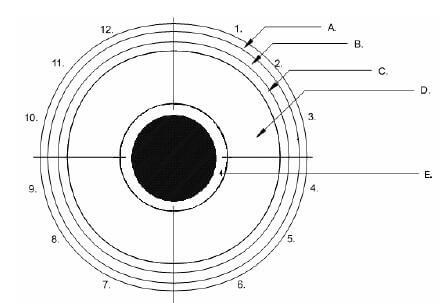
A5.2.4 Divide the tube periphery into four separate quadrants. Mark the intersection of the aluminum foil wrap ends 12 O’clock. From there moving clockwise, mark each subsequent section 3, 6, and 9 O’clock with respect to the 12 O’clock position. In each quadrant field of view take three random readings which include the minimum thickness value (See Figures A2 and A3). Report each of the three readings per quadrant, 12 readings total, for both the zinc-aluminum and epoxy paint or nylon layers, and for the nickel plating when it is specified.
A5.2.5 Record all thickness values and compare to the applicable sections of GM123M/GM124M. The required minimum thickness values are as follows:
| Code | GE/P | GN | GE/Ni |
| Zinc-aluminum alloy (min μm) | 3.0 | 3.0 | 3.0 |
| Aluminum rich epoxy paint (min μm) | 3.0 | – | 3.0 |
| Nylon 11 or 12 (min μm) | – | 150 | – |
| Nickel | – | – | 3.0 |