
1 Scope
This standard applies to brake pipes with and without flares for installation in hydraulic braking systems.
2 Dimensions, designations
2.1 Pipes without flares
B Double-walled rolled pipe
C Welded and drawn pipe
D Seamless drawn pipe
Designation of a double-walled rolled steel brake pipe without flare complying with Table 6(B), with an outer pipe diameter d1 = 6 mm:
Pipe DIN 74234 – B6
Order specification for the same brake pipe with a length of 5 m:
Pipe DIN 74234 – B6 × 5000
| Outside Diameter ¹⁾ ²⁾ | Wall thickness of pipe | Burst pressure, minimum, | Weight, kg/m | ||||
| d1 | B | C. | D | bar | B | C | D |
| ± 0,07 | ±0.07 | Tolerances | ±0.075 | ||||
| 4.75 | 0.7 | 0,75 ± 0,075 | 0.75 | 1100 | 0.07 | 0.08 | 0.08 |
| 6 | 0.7 | 0,75 ± 0,075 | 0.75 | 850 | 0.09 | 0.10 | 0.11 |
| 8 | 0.7 | 0,75 ± 0,075 | 0.75 | 675 | 0.12 | 0.15 | 0.15 |
| 10 | 0.7 | 1.00 ± 0.1 | 0.75 | 550 | 0.16 | 0.20 | 0.19 |
2.2 Brake pipe with flare
Brake pipes with flare may be fitted with brake pipe fittings according to DIN 74233 Part 1 or Part 2 as specified in Table 2.
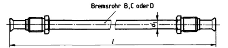
Designation for a brake pipe assembly with Form E flare consisting of two slipped-on union screws Form ES, brake pipe B with outer diameter (d1) = 6 mm and length l = 540 mm:
Brake pipe DIN 74234 – E – ES – B6 × 540
Table 2 Brake pipes with slipped-on brake pipe fittings
| Brake pipe B, C or D with flare | With brake pipe fitting | Quantity |
|---|---|---|
| Form E | Union screw DIN 74233 – ES | 2 |
| Union nut DIN 74233 – EM | 2 | |
| Form F | Union screw DIN 74233 – FS | 2 |
| Union nut DIN 74233 – FM | 2 |
Table 3
| l | up to 500 | over 500 up to 2000 | over 2000 up to 5000 | over 5000 up to 7000 | over 7000 |
|---|---|---|---|---|---|
| Limit dimension | +2 0 | +3 0 | +5 0 | +10 0 | By agreement |
2.3 Flare
2.3.1 Form E
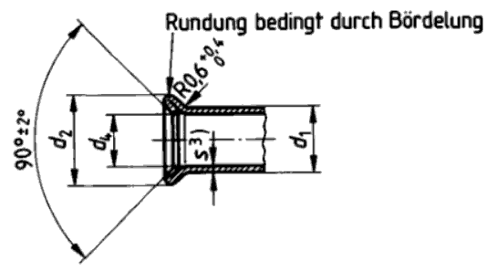
Radius formed by flaring.
Designation of a Form E flare for a brake pipe with outer diameter (d1) = 6 mm:
Flare DIN 74234 – E6
Table 4
| Outer diameter d1 | d2 js14 | d4 +0.3 −0.2 |
|---|---|---|
| 4.75 | 7.0 | 3.2 |
| 6 | 8.5 | 4.5 |
| 8 | 10.9 | 6.5 |
| 10 | 13.4 | 8.5 |
³) Values see Table 1
2.3.2 Form F
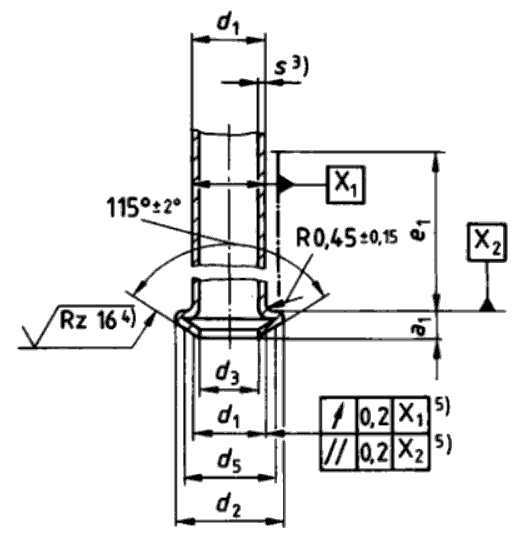
Designation of a Form F flare for a brake pipe with outer diameter (d1) = 6 mm:
Flare DIN 74234 – F6
Table 5
| d1 | d2 js14 | d3 +0.3 −0.2 | d5 min. | e1 min. | a1 ±0.3 |
|---|---|---|---|---|---|
| 4.75 | 7.1 | 3.2 | 5.0 | 17 | 2.3 |
| 6.00 | 8.4 | 4.5 | 6.0 | 18 | 2.5 |
| 8.00 | 10.7 | 6.5 | 8.0 | 24 | 2.6 |
| 10.00 | 12.7 | 8.5 | 10.0 | 28 | 2.9 |
³) Values see Table 1
⁴) Measured on a diameter between (d3) and (d5)
⁵) Measured on diameter (d1)
3 Material and strength properties
Table 6 Strength values for non-straightened tubes
| Brake pipe | Material grade (or material number) | Tensile strength N/mm² | Yield strength / 0.2% proof stress N/mm² | Elongation at fracture A5 % | Flaring test to DIN 50135 |
|---|---|---|---|---|---|
| B and C | Steel⁵) | min. 290 | min. 200 | min. 25 | Min. 20% internal diameter expansion |
| D | CuNi10Fe1Mn (2.0872) to DIN 17664 | min. 300 | min. 160 | min. 25 |
⁵) At manufacturer’s discretion
Note: Brake pipes complying with Section 2.1 exhibit different alternating bending fatigue strength, corrosion resistance and contact corrosion behaviour. This shall be considered during pipe routing and fixing. Relevant values shall be obtained from the manufacturer.
4 Execution
The inner and outer surfaces shall not show any rust. The outer surfaces of the brake pipes shall withstand the 240 h salt spray test DIN 50021 – SS without base metal corrosion.
5 Cited Standards
DIN 17 664: Wrought copper alloys; Copper-nickel alloys; Composition DIN 50 021: Spray mist testing with various sodium chloride solutions DIN 50 135: Testing of metallic materials; Flaring test on tubes DIN 74 233 Part 1: Hydraulic brake systems; Brake pipe fittings; Union screws for brake pipes DIN 74 233 Part 2: Hydraulic brake systems; Brake pipe fittings; Union nuts for brake pipes.