0. FOREWORD
0.1 This Indian Standard was adopted by the Indian Standards Institution on 15 July 1976, after the draft finalized by the Steel Tubes, Pipes and Fittings Sectional Committee had been approved by the Structural and Metals Division Council.
0.2 There has been a long felt need for copper brazed steel tubes used specially in automotive, refrigeration and stove industries for fuel lines, brake lines, oil lines and in heating and cooling units. It is hoped that this standard will give necessary guidance to the industry and users.
0.3 In the preparation of this standard assistance has been derived from ASTM : A 254-1970 ‘ Specification for copper brazed steel tubing ’ issued by the American Society for Testing and Materials.
0.4 For the purpose of deciding whether a particular requirement of this standard is complied with, the final value, observed or calculated, expressing the result of a test or anaLyysis, shall be rounded off in accordance with IS : 2-1960*. The number of significant places retained in the rounded off value should be the same as that of the specified value in this standard.
1. SCOPE
1.1 This standard covers two classes of copper brazed steel tubes suitable for general engineering uses, particularly inthe automotive, refrigeration, and stove industries for fuel lines, brake lines, oil lines, heating and cooling units, etc.
2. SUPPLY OF MATERIAL 2.1 General requirements relating to the supply of copper brazed steel tubes shall conform to IS : 1387-1967.
3. MANUFACTURE
3.1 The steel shall be aluminium-killed, rimming or capped Steel and shall be made by the open hearth, electric furnace, basic oxygen or a combination of these processes.
3.2 The tubing shall be made by rolling electrolytically copper plated steel strip in the form of tubes and subsequently brazing in a reducing atmosphere.
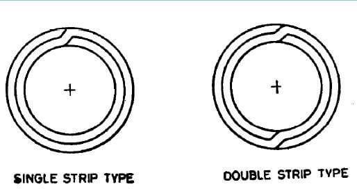
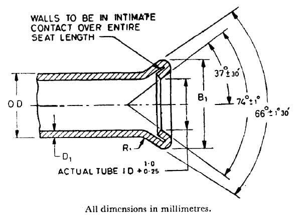
3.3 Class 1 brazed tubes shall be constructed as shown in Fig. 1.
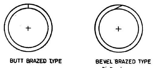
3.4 Class 2 brazed tubes shall be constructed as shown in Fig. 2.
4. CHEMICAL REQUIREMENTS
4.1 The steel when analyzed in accordance with relevant parts of IS: 228 shall conform to the following requirements:
| Element | Percent, Max |
|---|---|
| Carbon | 0.10 |
| Manganese | 0’50 |
| Phosphorus | 0.035 |
| Sulphur | 0.035 |
4.2 Each heat shall be analyzed by the steel manufacturer to determine the percentages of the elements specified in 4.1. The chemical composition thus determined shall be reported to the steel purchaser, or his representative, and shall conform to the requirements specified.
5. MECHANICAL REQUIREMENTS
5.1 Tensile Test -Test pieces shall be taken from the ends of tubes (prior to cold-work) and tested in accordance with IS : 1894-19727 and shall comply with the following requirements:
| Tensile Strength | 290 N/mm2, min |
| Yield Strength | N/mm2, min |
| Elongation on a gauge length of 65mm | N/mm2, min |
5.2 Flattening Test-The test shall be conducted in accordance with IS : 2328-1963:. A ring not less than 65 mm in length, cut from one end of each selected tube shall, when cold, be flattened between two parallel flat surfaces without showing any crack or flaw, until the inside walls are in contact. In case of Class 2 tubes, the seam shall be located so as to receive the maximum deformation upon flattening.
5.3 Expansion Test – It shall be carried out in accordance with IS : 2335-19635. A section of tube approximately 50 mm in length shall withstand being expanded over a tapered mandrel or cone having an included angle of 30” until the outside diameter at the expanded end is increased 20 percent without cracking or otherwise showing flaws. Prior to expansion test, tubes shall be cut off, square edge crowned and deburred. The tube and cone shall remain concentric during expansion tests.
5.4 Bend Test -The test should be carried out in accordance with IS : 2329-1963*. The tube selected ~for test. shah withstand bending around a cylindrical former through 360”, with the joint line at 90’- to the plane of bending. The diameter of the former shall be six times the outside diameter. The test piece shall withstand this test without kinking, cracking or developing other flaws.
5.5 Bending Shear Test – If a cut piece of tube bent by hand in the form of a hair pin (seam on inner side) shears-by reverse bending at bending radius in a direction perpendicular to the axis of the bend, neither should the walls of the tube separate nor should the seam get cracked.
5.6 Non-destructive Testing – The tubes shall be checked 100 percent for brazing and surface defects by non-destructive testing during production ( see IS : 4853-19687 and Is : 7343-1974:).
6. HYDRAULIC TEST
6.1 Each tube shall be capable of withstanding hydraulic test for a period of 5 seconds with no evidence of failure, at a pressure calculated by the following equation:
P=2St/D
where
P = hydraulic pressure in N/mm2;
S = allowable stress of material, that is;
11O N/mm? for Class I
45 N/mm2 for Class II;
t = wall thickness of tube in mm; and
D = outside diameter of tube in mm.
7. INSIDBURFACE CLEANLINESS
7.1 When specified by the purchaser, tubes for certain uses, such as refrigeration condensers, shall conform to the following requirements for internal cleanliness.
7.1.1 When a length of tube is washed, internally with redistilled chloroform or redistilled trichloroethylene, the residue remaining upon evaporation of the solvent shall not exceed 0.194 g/m*of internal surface. To perform the test, pour 100 ml of solvent through the tube and collect. The total length of tube tested shall be not less than 12.2 m, although this total length may be obtained by washing several separate lengths .and pouring the same solvent through each in succession. Evaporate the solvent on a steam-bath or hot water-bath and dry at 110°C until the vapours are Completely removed.
7.2 To maintain this level of cleanliness in shipping, handling, and storage, the purchaser may request the manufacturer to seal tube ends with caps or closures.
8. DIMENSIONAL TOLERANCES
8.1 Tubes shall conform to permissible variations in dimensions as specified below:
| Outside Diameter | |
| Below 4.8 mm | ±0.05 mm |
| 4.8 mm up to and including 95 mm | ±0.08 mm |
| Over 9.5 mm up to and including 15.9mm | ±0.10 mm |
| Wall Thickness | |
| 0.50 mm up to and including 0.76 mm | ±0.08 mm |
| Over~0.76 mm up to and including 1.25 mm | ±0.09 mm |
| Length | |
| Up to and including 0.5 m | ±0.75 mm |
| Over 0.5 m up to and including 1.0 m | ±1.5 mm |
| Over 1.0 m up to and including 2.0 m | ±3.0 mm |
| Over 2.0 m up to and including 3.0 m | ±6.0 mm |
| Over 3.0m | +25.0 mm -0.0 mm |
9. WORKMANSHIP
9.1 Finished tubes shall be clean, smooth and round, both inside and outside and shall be free from rust, scale and defects which impair processing and serviceability. Finished tubes shall be reasonably straight.
10. SUPPLEMENTARY RIQUIREMENTS
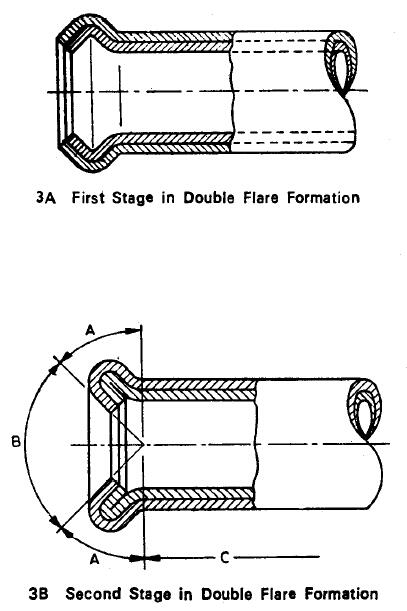
10.1 Flare Test -Class 1 tubes shall stand being double flared to the dimensions shown in Tables 1 and 2. The double flaring shall be done on square, deburred tube ends, using a hand tool or powered press, in two stages. Jn the first stage a tool forms the upset (see Fig. 3A ), while in the second stage another tool gives the final shape ( see Fig. 3B).
The tubes shall not split through the wall at the major diameter of the flare. A separation of the outer lap joint is permissible on the flared end of the tube only in area A (see Fig. 3 ). This separation shall not exceed 3.0 mm in length and shall be confined to outer thickness only. Seam separation is not permitted in the following areas:
a) Area B (the flare seat, defined as the surface within the 90° included angle): conical surface shall be smooth and free from cracks or other irregularities that could cause leaks after assembly.
b) Area C ( the surface beyond the length of the double thickness cracked by the flare ).
| NOMINAL OUTSIDE DIAMETER | DOUBLE FLARE DIA, B1 | COINED LENGTH C1, Min | Wall Thickness D1 , Max | |
| Max | Min | |||
| 3.18 | 5.4 | 5.0 | 1 | 0.63 |
| 4.76 | 7.1 | 6.7 | 1 | 0.71 |
| 6.35 | 9.1 | 8. 7 | 1 | 0.88 |
| 7.94 | 10.8 | 10.4 | 1.6 | 0.88 |
| 9.52 | 12.7 | 12.3 | 1.6 | 1.24 |
| 11.11 | 14.5 | 14.1 | 1.6 | 1.24 |
| 12.7 | 16.3 | 15.9 | 1.6 | 1.24 |
| 14.29 | 18.1 | 17.7 | 1.6 | 1.24 |
| 15.88 | 19.6 | 19.2 | 1.6 | 1.24 |
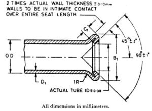
| NOMINAL OUTSIDE DIAMETER | DOUBLE FLARE DIA, B1 | COINED LENGTH C1, Min | Wall Thickness D1 , Max | |
| Max | Min | |||
| 3.18 | 5.1 | 4.6 | 0.8±0.5 | 0.63 |
| 4.76 | 7.1 | 6.6 | 0.8±0.5 | 0.71 |
| 6.35 | 9.1 | 8.6 | 0.8±0.5 | 0.88 |
| 7.94 | 10.9 | 10.2 | 0.8±0.5 | 0.88 |
| 9.52 | 12.4 | 11.7 | 1.0±0.5 | 1.24 |
| 12.7 | 16.7 | 16.0 | 1.0±0.5 | 1.24 |
| 15.88 | 20.0 | 19.3 | 1.0±0.5 | 1.24 |
10.2 External Coating -The outside surface of the tubes shall have a coating of hot-dipped lead-tin alloy-coating or electroplated zinc as specified by the purchaser. Weight and other requirements of coating shall be agreed upon between the manufacturer and the purchaser.
10.3 End Finish -When so specified by the purchaser, finished tubes shall have smooth ends free of burrs.
11. MARKING
11.1 The following information shall be marked on a tag or label securely attached to the bundles or boxes in which the tubes are dispatched:
a) Manufacturer’s name or trade-mark,
b) Size, and
c) Class of tubes.
11.1.1 The tubes may also be marked with the ISI Certification Mark.
NOTE – The use of the ISI Certification Mark is governed by the provisions of the Indian Standards Institution ( Certification Marks) Act and the Rules and Regulations made the reunder. The ISI mark on products covered by an Indian Standard conveys the assurance that they have been produced to comply with the requirements of that standard under a well-defined system of inspection, testing and quality control which is devised and supervised by ISI and operated by the producer. ISi marked products are also continuously checked by ISi for conformity to that standard as a further safeguard. Details of conditions under which a licence for the use of the ISi Certification Mark may be granted to manufacturers or processors, may be obtained from the Indian Standards Institution.
12. INFORMATION TO BE SUPPLIED BY THE PURCHASER
12.1 The purchaser shall state in his enquiry or order:
a) the size ( outside diameter, wall thickness and length of tubes);
b) the class of tube required;
c) the inside surface cleanliness where require&d;
d) the external coating where required; and
e) special requirements, if any.